
Rework of electronic assemblies with Hybrid Rework Systems
With strong price/performance ratios and patented hybrid rework technology, Ersa Rework Systems have placed themselves at the top of the market. Even in the most challenging SMT/BGA rework applications, they deliver repeatable best-in-class results. Ersa Rework Systems embody successful rework from the very first process.


Sustainable SMT/BGA Repair Ersa Rework Technology

Maintaining Added Value with Professional Rework of Electronic Assemblies on Ersa Rework Stations
A lot of time, money, material and expertise are used in electronics production. This makes the ability to professionally rework assemblies with Ersa rework systems all the more important in order to sustainably secure this added value. A high level of expertise and state-of-the-art equipment are necessary to carry out prototyping and rework work professionally. The right rework system must have the appropriate technologies to ensure efficient, successful processing.

Selective Rework of SMD Components
The term rework refers to the combination of all sub-processes to selectively install or replace individual SMT components of an assembly. First, an SMD component is desoldered from the assembly. Then the residual solder is removed and the assembly is prepared to install a new component. This is followed by precise placement and soldering of the new component. The processing of almost all SMD component shapes is possible here. The goal of rework or sample production: Produce products that are equal in quality to those produced in series.
Why rework? The reasons for reworking electronic assemblies are as varied as the electronics themselves. The following causes are common:
- There is a defect in the component
- The wrong component has been assembled
- The component was assembled in the wrong orientation
- A component has been poorly soldered (bridges, open solder joints, etc.)
- Use more powerful, compatible components in the circuit (upgrading)
- A component is saved for reuse (recycling)
- A change is made to the assembly (redesign)
- Assembly is set up as a prototype and part(s) are reassembled
- The assembly is tested, e.g. cross-exchange (testing)
- Component data from a defective assembly must be saved (forensics)
- A component is programmed incorrectly
The aim of reworking is always to obtain a functional and reliable assembly at the end. In addition, there is the motivation to reduce the amount of electronic waste in terms of sustainable management.

Powerful Features for Rework: Desoldering & Heating
Desolder component

Desolder component
To desolder a component, the system follows a temperature profile guided by a sensor. Top emitters and IR bottom heating provide the necessary energy for this. The target component is automatically lifted off the board with a vacuum pipette when the solder is liquid. For optimal heating, the entire assembly must be considered: Neighboring components are just as relevant for process control as the assembly on the underside of the board.
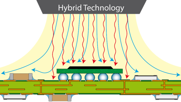
Hybrid Top Emitter
Hybrid Top Emitter
The hybrid heaters of the heating heads consist of highly efficient, medium-wave infrared emitters and heat the target component gently and homogeneously. The radiation spectrum is characterized by very good absorption by components and board materials. Very small temperature differences (delta T) occur and thus hardly any thermal stresses in the joining partners. The additional convection component heats the components even faster and in a more targeted manner.
IR Preheating

IR Preheating
The infrared bottom heating is used to preheat the circuit board as homogeneously as possible over the entire surface and is a core component of every hybrid rework system. Preheating the board over a large area is particularly important for larger assemblies in order to minimize warpage and deflection. Particluar zones of the bottom heating can be set individually and thus adapted to the PCB and the components. Even "hot spots", where the heat input is specifically directed to one area, or cold zones to protect the PCB or components can be defined. Added to this is a coherent board fixture concept with effective PCB support.

Remove Residual Solder
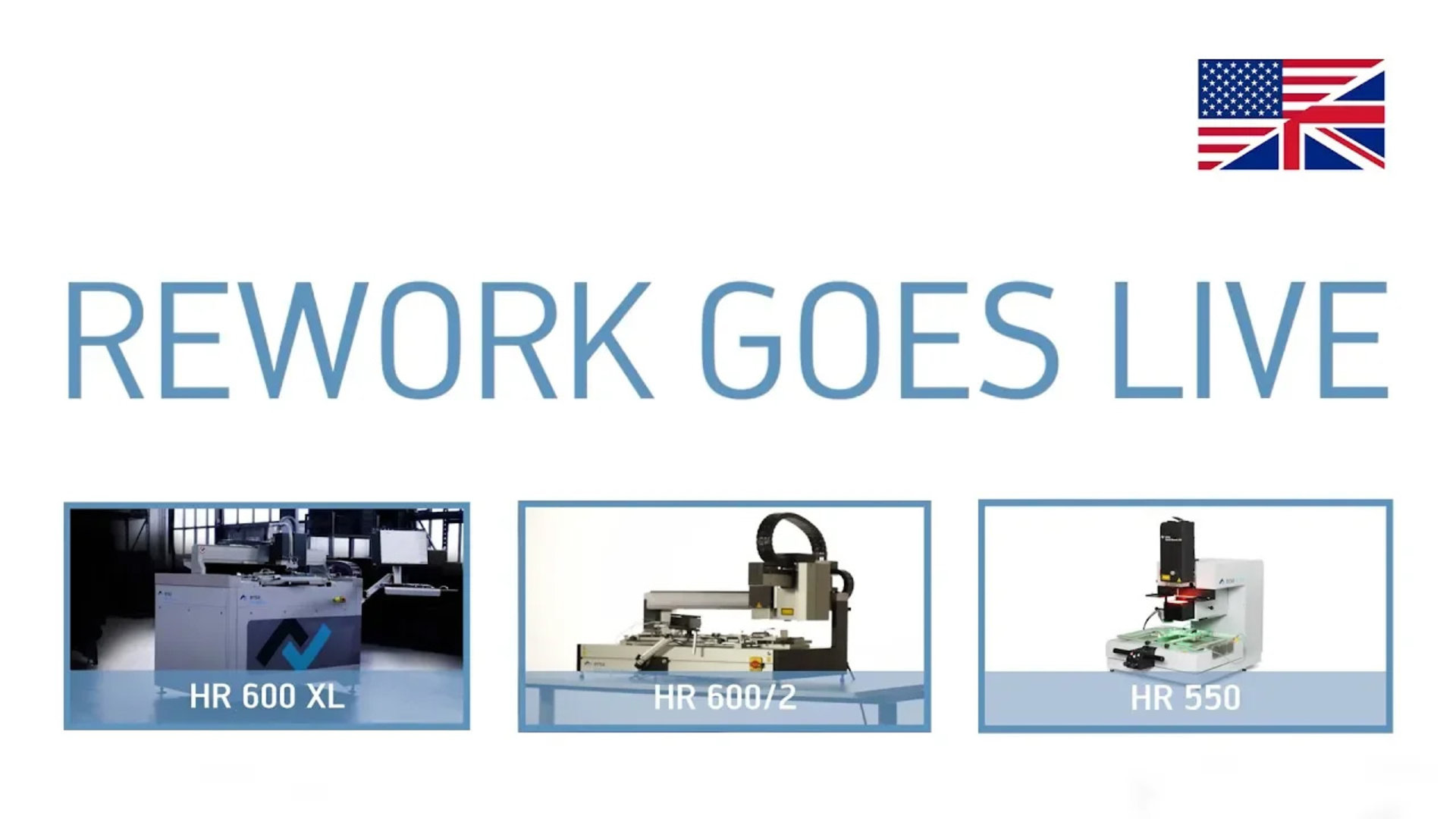
An important step before installing a new component is to remove any remaining solder on the solder terminals. A suitable soldering tool with a suitable soldering tip can be used for this purpose. If the assembly is to be cleaned of solder without contact, hot gas modules are used. A manual or an automatic module for residual solder removal can be adapted to the Ersa rework systems - e.g. HR 600 XL.
Ersa Scavenger are hot gas modules which are used to extract residual solder from the circuit board without contact. For this purpose, the board is kept at temperature after desoldering the component. A hot gas head moved manually or automatically over the board melts the solder and it is extracted by vacuum. The previously remaining unevenness is eliminated. After the residual solder has been extracted, the assembly should be cleaned of further residues such as flux.

Apply Solder Paste or Flux
To install a new component, fresh solder or flux (e.g. for ball grid arrays) is required. Since the packing density of electronic assemblies is very high, there is rarely space to print solder paste or flux onto the board. Dispensing processes are usually very time-consuming and manual application is too imprecise. Therefore, Ersa offers with the Dip&Print Station the possibility to prepare components with solder paste or flux in order to place and solder them safely afterwards.
Dip&Print: Rework fluxes are available as viscous media and can be processed similarly to solder pastes. With the Dip&Print station, templates with suitable cavities (recesses) can be used to dip the connections of the component to be installed (e.g. BGA) into a suitable flux deposit (dip-in). A defined volume is thus created at each connection. Flux or dip-capable solder pastes can be processed.
Alternatively, individually manufactured stencils are used to print a component with solder paste. The printed component is lifted out of the stencil and then placed. With this method, exact paste volumes can be applied, for example, to bottom terminated components (BTC). Floating of components is prevented, and optimum thermal bonding to the board is ensured.

Place Component
The new target component is provided at the rework system and picked up with a vacuum pipette. The component is aligned with the solder connections on the board by means of an optical overlay. A user-guided or fully automatic process is used for this. When the component is precisely aligned, it is placed on the board and the soldering process can begin.
The user-guided placement process is based on a camera image in which the underside of the component and the board are recorded simultaneously. The beam splitter required for this is located in the vision box between the component and the board. This simultaneously provides the LED illumination. The user checks the superimposition of the two joining partners and aligns them to each other. He is optimally supported by the necessary magnifications and different display modes.
In the fully automated placement process, component connections and solder connections are recorded by two different cameras and the images are then superimposed using image processing algorithms. The movement coordinates are calculated from the optimum component position and the component is automatically placed on the board using a high-precision axis system.
 parallel to real-time temperature recording")
Soldering & Monitoring
As for desoldering, the same system components are used for soldering in the new component. Nevertheless, the processes differ: During soldering-in, the component initially does not have good thermal contact with the board and, in some cases, an adapted soldering-in profile is required. A reflow process camera (RPC) observes the soldering process and provides the user with valuable, additional information about the course of the process.
In addition to the high-resolution images, further sensors help to make the rework process even more stable and reproducible: During a soldering process, the current gradient of the solder curve and the condition of the top emitter are monitored. The user receives messages if a process deviates too much from the specifications. A non-contact sensor can be calibrated - currently on the HR 600 XL - with the process data of a thermocouple. After successful teach-in, all subsequent processes on the same component on identical boards can be controlled via this "virtual TC" sensor.

Document Processes
Under the keyword "Enhanced Visual Assistant" (EVA), the user interface of HR Soft 2 offers the user all the help they need to complete rework tasks reliably and quickly. Users can quickly find their way around the clearly structured software. Predefined soldering and desoldering profiles are easy to select, the user is guided safely through all rework process steps, with easy-to-understand pictograms and explanatory texts.
For computer-aided placement of components, HR Soft 2 provides the user with high-contrast, high-resolution images of the PCB and component connections. In this way, all SMD designs can be aligned quickly and without fatigue for the user. Special tools such as digital split optics for aligning large QFPs, together with a database-based archive and other useful functions, round off the performance spectrum of HR Soft 2. The HR 500, HR 550, HR 550 XL, HR 600/3P and HR 600 XL are currently operated with HR Soft 2. It is also the communication interface for connections to Manufacturing Execution Systems (MES).

In electronics production, it can happen that components are displaced from their intended position on the PCB. Avoid electronic waste and replace the component with an Ersa rework system.
Individual online demos for all Ersa rework systems. The Ersa experts will show you live how to operate the devices and solve the rework tasks using your circuit boards.

